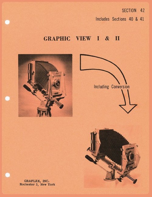
Product Description
Graflex Graphic View Camera I & II
1 . INTRODUCTION
This section of the Service Parts Manual covers the Graphic View, Model I and II. The text and illustrations cover disassembly, cleaning, reassembly, conversion, troubles and lubrication. The Graphic View His illustrated since the two cameras are similiar in construction and service; however, the differences are described in the text and parts list. The parts list indexes to these illustrations. Always refer to parts by the part number and name... never by the index number in correspondence and orders.
2. INSPECTION AND TROUBLES
Many of the troubles encountered by the repairman will be very obvious, while others will not be too apparent. Before disassembly, check for loose or missing screws or parts that are binding due to lack of lubrication or misalignment of parts.
Inspect the camera as follows:
B. The shift lock spring (5-1) that indicates center position on the front and back carriage lateral shift and horizontal swing should be strong enough to indicate correct centering position.
C. The focusing shaft knob (4-7) should turn smoothly and not bind during its rotation.
D. Look for loose screws on tripod head, back springs, focusing lock, front and back pivot, and lock knobs.
E. Check the rising front. Be sure it locks when the shaft is moved to the left. With the rising front pinion to the left, as in the unlocked position, there should be 1/32 inch space between the right (locking) knob and front casting and 3/16 inch space between the left knob and front casting.
F. Check the bellows for pin holes by extending the bellows and inserting a light. Check corner folds where cracks are most likely to occur.
G. If the bed rack has shifted, adjust so that the... (continued)


