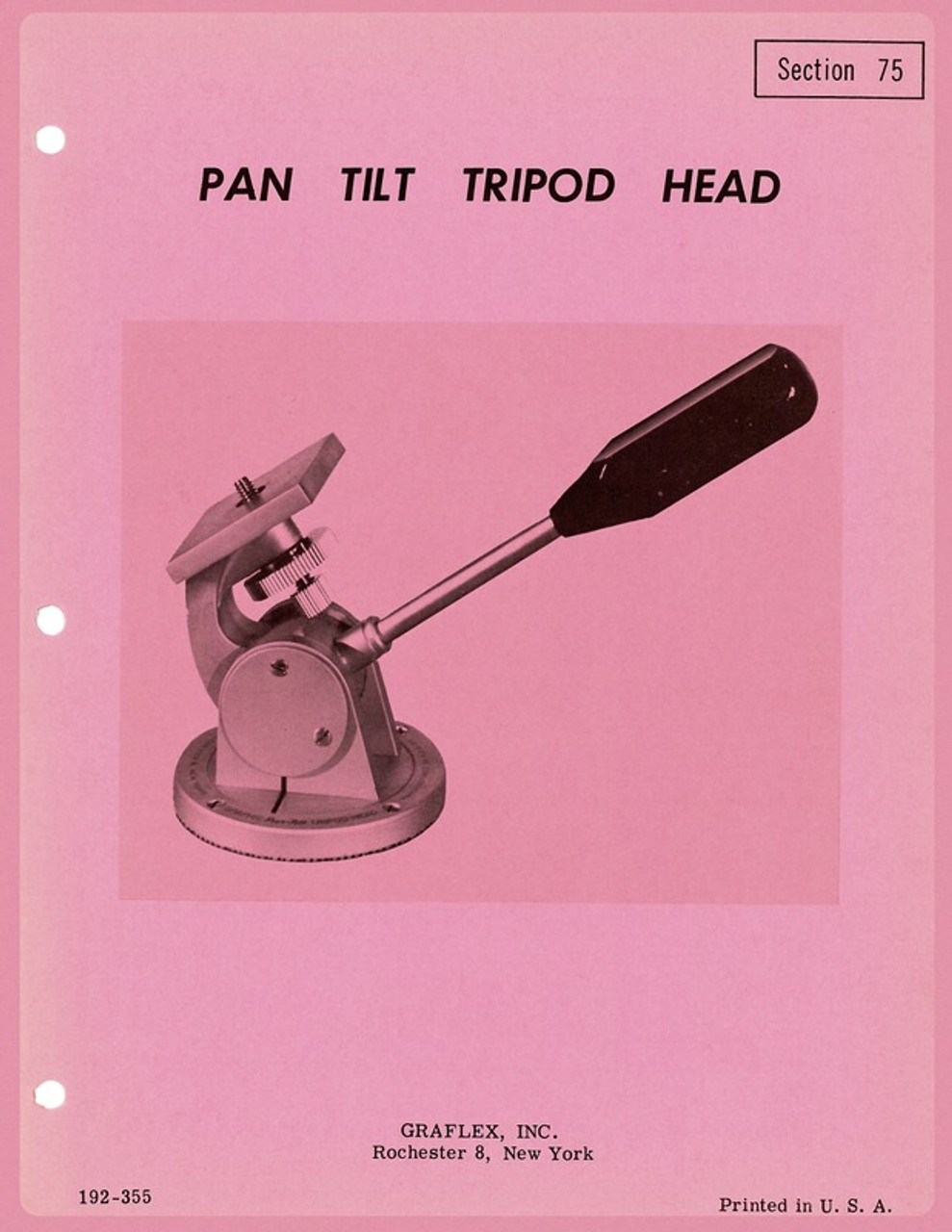
Product Description
Graflex Pan Tilt Tripod Head
Service Instructions & Parts Catalog - Section 75
1. Disassembly
A. Remove handle (1-1).
B. Remove support assembly from base (1-18) by removing four screws (1-2) and base cover plate (1-17).
C. If necessary, remove base pad (1-19) from base (1-18).
D. Remove two screws (1-10) from each support end plate (1-9).
E. Remove clamp lock plate (1-11).
F. Remove two screws (1-13) from each of the barrel supports (1-12).
H. If necessary to remove camera clamping screw (1-6) remove threaded bushing (1-3), spring (1-4), washer (1-5) and remove screw support cap (1-8) and adjusting nut (1-7) from screw (1-6).
B. Remove support assembly from base (1-18) by removing four screws (1-2) and base cover plate (1-17).
C. If necessary, remove base pad (1-19) from base (1-18).
D. Remove two screws (1-10) from each support end plate (1-9).
E. Remove clamp lock plate (1-11).
F. Remove two screws (1-13) from each of the barrel supports (1-12).
— CAUTION —
Care should be taken to evenly lift the barrel supports that are doweled so that the dowel holes will not be damaged.
G. The support assembly (1-15) may now be removed from (1-16).Care should be taken to evenly lift the barrel supports that are doweled so that the dowel holes will not be damaged.
H. If necessary to remove camera clamping screw (1-6) remove threaded bushing (1-3), spring (1-4), washer (1-5) and remove screw support cap (1-8) and adjusting nut (1-7) from screw (1-6).
2. Service
A. Clean all parts with trichlorethylene (AN-T-37a) or carbon tetrachloride.
B. Dry all parts thoroughly and replace any defective parts.
C. Lubricate the moving surfaces with #107 Lubriplate and reassemble.
B. Dry all parts thoroughly and replace any defective parts.
C. Lubricate the moving surfaces with #107 Lubriplate and reassemble.
3. Reassembly
A. Insert screw (1-6) into camera support assembly (1-15) and assemble lock nut (1-7).
B. Assemble support cap (1-8) to screw (1-6) and tighten securely.
C. Assemble washer (1-5) and spring (1-4) to screw (1-6) and secure with threaded bushing (1-3).
D. Reassemble the camera support (1-15) and the barrel supports (1-12) each with two screws (1-13) to the two sections of the rotating plate (1-16) and then drive dowel pins (1-14) in place.
E. If the dowel pins have not been used then the drawing in figure 2 should be followed. If the, present dowel holes have been distorted they may be reamed larger to accomodate a slightly larger dowel pin. Drill or ream the hole about .0007’ smaller than the dowel pin being used.
F. Slide the clamp lock plate (1-11) into the barrel from the side and reassemble end plates (1-9) each with two screws (1-10).
G. If old base pad (1-19) was removed from base plate (1-18) cement a new base pad in place with EC-880... (continued)


